
Energy recovery improves the energy efficiency of the electric power supply installation for traction on conventional rail networks and reduces emissions into the atmosphere. Ineco’s first task was to draft the construction project for the installation of a regenerative braking energy recovery unit in the traction substation of La Comba in the province of Málaga, which was put into service in 2014. This is the only installation of its type in service on the conventional network (see ITRANSPORTE 44). The recuperator has made it possible to return more than 1 GWh/year to the power grid, representing an annual savings of more than 12.5% on the energy consumption of the Málaga-Fuengirola line, reducing CO2 emissions by around 230 tons/year (based on a conversion factor of 0.23127 kg of CO2 per kWh). The investment is expected to be recouped within a less than 10 years.
The success of this first energy recuperator prompted Adif to install recovery units in other substations. Since 2015, simulations on national gauge have been carried out to identify substations with the greatest capacity for energy recovery. Railway installations have been modelled taking into consideration data relating to rolling stock, traffic grids, geometric railway platform profiles, electrification installation characteristics, driving modes, etc.
The recovery of regenerative braking energy on the conventional network is one of the measures included in Adif and Adif HS’s Energy Saving and Efficiency Master Plans. It is also one of the energy efficiency actions included in the Programme of Subsidies for Energy Efficiency Initiatives in the Rail Sector (Resolution of 30 November 2015, BOE-A-2015-13117) offered by the Institute for Energy Diversification and Savings (IDAE). The funding provided by this body for the exploitation of braking energy covers 30% of the investment. Adif plans to have 12 new energy recuperators in service between 2019 and 2020, and is considering extending the installation of these units across its network, mainly on commuter lines.
Putting 12 new recovery units into service
The first simulations carried out by Adif in 2015 and 2016 on several conventional railway lines identified the substations of Alcorcón, Getafe, Guarnizo, Olabeaga, Martorell and Arenys de Mar as the ones with the greatest capacity for recovering energy and, therefore, the ideal candidates for the installation of recovery units. For these six installations, Ineco prepared the documentation for submitting subsidy applications to the IDAE (successfully awarded in January 2017), drafted the construction projects for the installation of the recovery units and is currently providing the works management and technical assistance. In 2017, Adif carried out a second series of simulations and selected the substations in Tres Cantos, Alcalá de Henares, Pinto, Leganés, Granollers and Castellbisbal. For these, Ineco also prepared the subsidy applications (successfully awarded in February 2018), drafted the construction project and will be providing the works management and technical assistance. It is expected that the first group of substations will be in service by mid-2019, and the second group by 2020.
These 12 recuperators are expected to save some 18.5 GWh/year, which represents a reduction in CO2 emissions of close to 4,300 t/year and a financial savings of over 1.3M/year. With IDAE’s 30% funding, it is expected that the investment of more than 8M will be recouped in approximately 6 years. New simulations will continue to be carried out in the hope of further extending the installation of recovery units across the entire conventional railway network.
Theoretical basis
When trains use rheostatic or regenerative electric brakes, they transform the train’s kinetic energy into electrical energy. Their engines act as generators, slowing down the wheels and performing the energy conversion. Some of this energy is used to supply the train’s auxiliary services, and the rest, in the case of regenerative brakes, is transferred to the overhead line, increasing its voltage.
The first regenerative braking energy installation in the traction substation in La Comba has made it possible to return 1 GWh/year to the power grid.
Part of the energy fed to the overhead line is used by other trains that require it at the moment that it is regenerated, and the surplus is either sent back to the electrical grid if the traction substations are reversible (enabling a two-way transfer of energy: from the grid to the overhead line and vice versa) or it dissipates in the form of heat in the braking resistors installed on board the trains if the substations are not reversible.
Traction substations on high-speed lines use alternating current (AC), which means that they are reversible. However, substations in direct current (DC) electrification systems, such as metros, trams, conventional railway lines, etc., are not reversible because the change to DC requires rectifiers that only allow energy to flow in one direction, from the electrical grid to the overhead line.
The figure shows the general schematic for the energy recovery installation in the La Comba substation.
In order to make conventional substations reversible, a current inverter (DC/AC converter) must be installed in the substation, along with certain interface elements, such as DC and AC huts, wiring, electrical panels, control and remote control systems, etc. Together, all of these elements make up the braking energy recuperator.
The energy recuperator detects when there is a surplus of braking energy in the overhead line and allows the inverter to operate so that it can convert this electrical energy, in the form of DC present in the overhead line, into AC and feed it into the power grid.
The inverter load cycle
Ineco has collaborated with Adif on the selection of the load cycle of the inverters to be installed on its conventional network. Similar to other units installed in traction substations, such as rectifiers and transformers, the inverter must be a standard unit that can be installed in different substations on the conventional network, and not specifically designed for individual facilities.
Following the electrical simulations that resulted in the selection of the Alcorcón, Guarnizo and Olabeaga substations, information was made available to characterise the recoverable power.
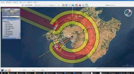
The graph below shows a typical recoverable power profile. The peaks represent pulses caused by train braking whose amplitude, as well as duration and separation in time, is variable.
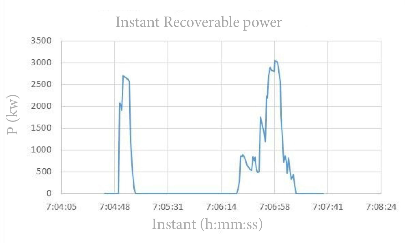
The parameters that characterise the pulses are: amplitude, duration of the pulses and time between braking.
To determine the load cycle of the inverter, defined as indicated below, the profile of dischargeable power was aligned with a sequence of pulses of constant amplitude, whose value is the RMS (Root Mean Square) of the instantaneous power values.
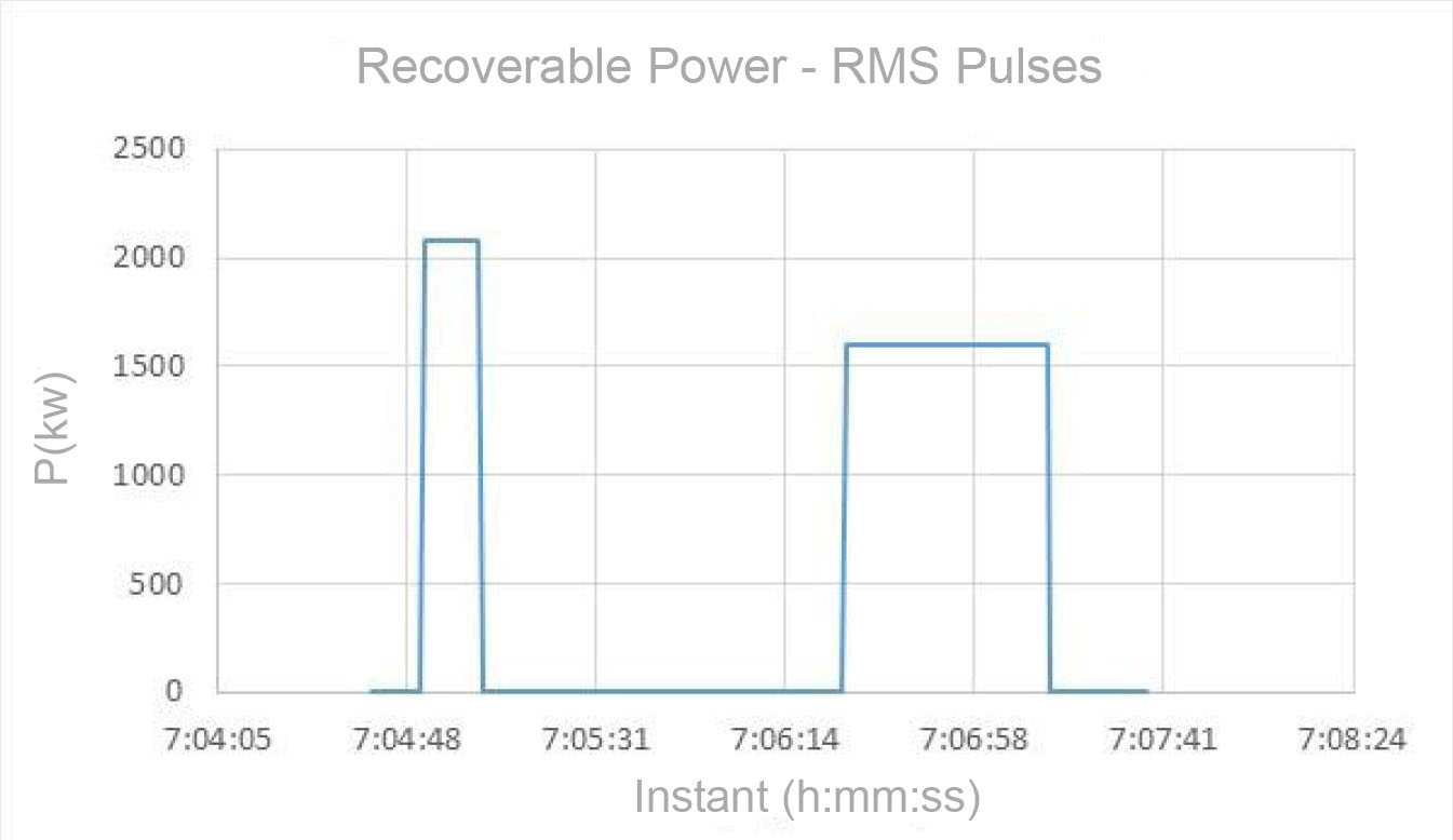
The inverter’s load cycle is defined based on the following parameters: maximum power (PMAX), maximum power pulse duration (T1) and cooling time (T2).
An inverter with the specified load cycle must be able to permanently transfer every T1+T2 seconds a power pulse with the value PMAX and duration T1 seconds. To recoup 100% of the energy discharged by trains in the substation environment, the envelope of the inverter’s load cycle should contain all recoverable power profiles. However, the optimisation of the ratio of investment cost/recovered energy, that is, the maximum energy recovered for economically reasonable inverter dimensions, determined that the load cycle of the selected inverter will be determined by the following values: PMAX= 2.5 MW, T1= 40 s and T2= 120 s.
An inverter with this power characteristic was able to recover the following percentages of dischargeable energy for the three simulations carried out for the load cycle determination study: Alcorcón substation > 73.15%, Olabeaga substation > 92.11% and Guarnizo substation > 99.97%.
A larger inverter would have made it possible to recover all of the available energy, but its cost would have made the investment unviable.
Another step in standardising the installation of energy recuperators was identifying the equipment that could be specified with precision, regardless of the specific design of the inverter by the technology company, in order to reduce the scope of supply of this company. This made it possible for energy recovery installations in different substations to differ only in the inverter and the equipment directly linked to its design, mainly DC and AC switchgears and filters, and transformers at the inverter output.
The design of energy recovery installations in conventional substations
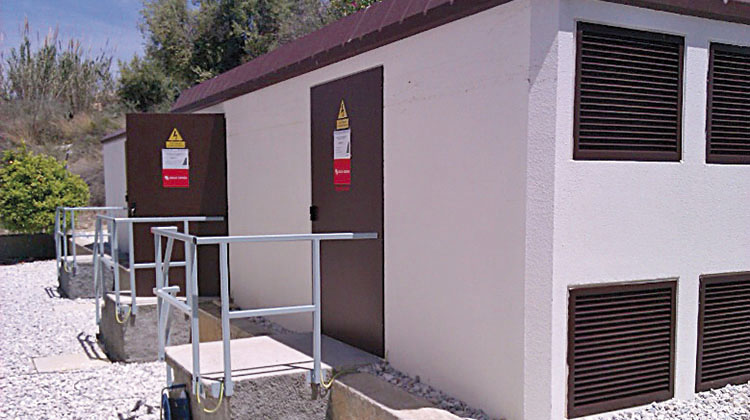
Because there is a lack of free space inside substation control buildings, energy recuperators need to be installed in two separate buildings designated as the operations hut and the inverter hut. The operations hut houses the substation interface equipment and the inverter hut, the inverter itself.
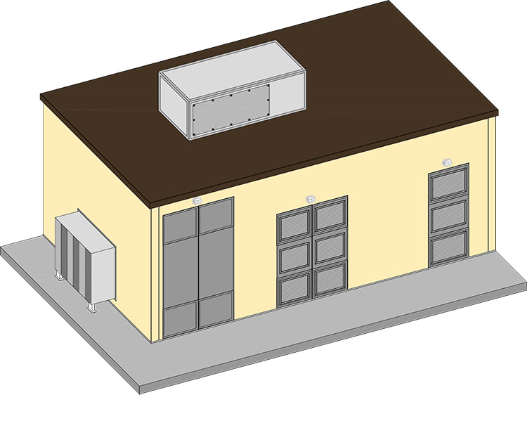
An operations hut.
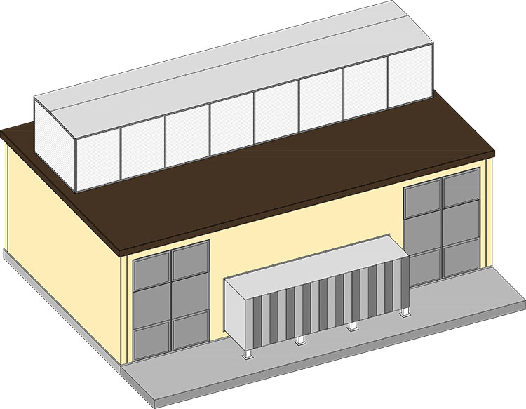
An inverter hut.
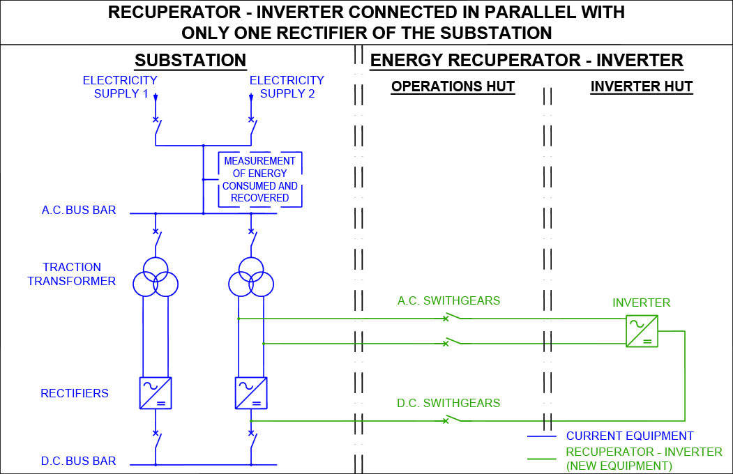
General schematic of an energy recovery installation
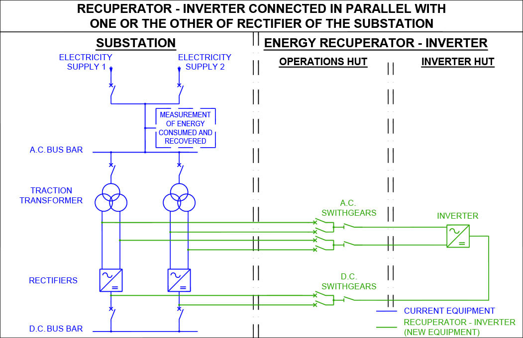
The general schematic of the energy recuperators to be installed in the substations of Alcorcón, Getafe, Guarnizo, Olabeaga, Martorell and Arenys de Mar (pictured) is different from the one implemented in the La Comba substation because the inverter can be connected in parallel to either one of the substation’s two rectifiers. This means that energy will always be recovered regardless of the mode of operation of the substation. In order to reduce the interface between the recuperator and substation, the recuperator’s connection to the substation has been modified. The new solution consists of connecting the recuperator between the substation’s DC busbar and general AC busbar downstream of the fiscal measurement equipment to allow reading of the energy returned to the grid. For this connection, a step-up transformer must be installed in series with the inverter to adjust the recuperator’s output voltage to that of the substation’s connection.
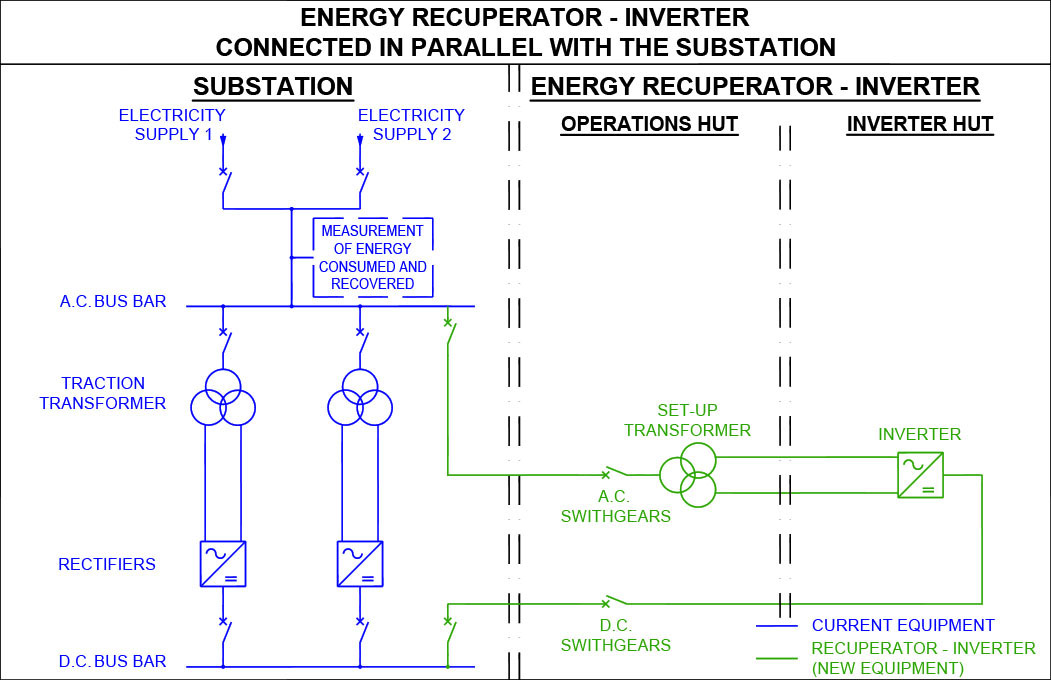
In the image, the schematic designed for the substations of Tres Cantos, Alcalá de Henares, Pinto, Leganés, Granollers and Castellbisbal and, if there are no new modifications, the one that will be adopted for future energy recovery installations in substations on the conventional network.